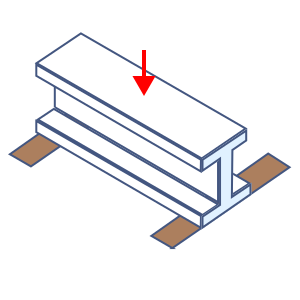
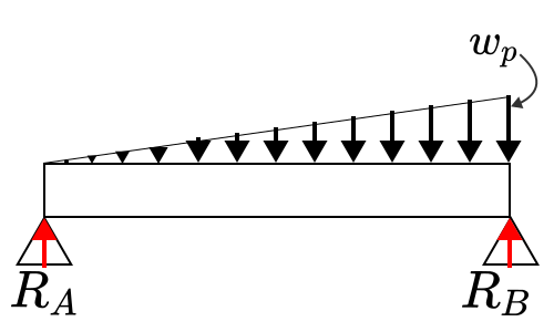
Gối đỡ hai đầu, tải phân bố tam giác — Nhôm định hình
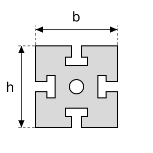
Tính độ võng và ứng suất khi dùng nhôm định hình (MISUMI HFS, SUS SF) làm dầm. Điều kiện tải trọng: Gối đỡ hai đầu, tải phân bố tam giác. Do mặt cắt có rãnh và khá phức tạp nên đặc trưng mặt cắt lấy theo giá trị nhà sản xuất công bố.
Đầu vào
Tải trọng phân bố
Chiều dài dầm
Mô đun đàn hồi Young
Chiều cao (phương uốn)
Chiều rộng
Gia tốc trọng trường
Kết quả
Khối lượng dầm
Tải trọng phân bố do trọng lượng bản thân dầm
Mô men quán tính mặt cắt
Mô đun chống uốn
Phản lực A
Phản lực
Mô men uốn lớn nhất
Độ võng lớn nhất
Ứng suất uốn lớn nhất
- Trích từ mục 8.1 "Độ võng của dầm" trong Tiêu chuẩn AIJ thiết kế kết cấu thép theo ứng suất cho phép, ban hành năm 2019.
- Dưới tác dụng của tải trọng dài hạn, độ võng của dầm không quá 1/300 nhịp, riêng dầm công xôn thì không quá 1/250 nhịp. Tuy nhiên, với xà gồ, thanh đỡ tường và các cấu kiện tương tự, có thể vượt giới hạn này trong phạm vi không gây ảnh hưởng đến vật liệu hoàn thiện.
- Khi hoạt tải tác dụng có tính động, phải kiểm tra dao động do độ võng của dầm để bảo đảm không ảnh hưởng đến tiện nghi sử dụng, khả năng vận hành thiết bị chính xác và năng suất.
- Với dầm đường chạy cầu trục, giới hạn độ võng là 1/500 nhịp đối với cầu trục quay tay và tương tự, còn với các loại cầu trục điện khác thì lấy 1/800 đến 1/1 200 nhịp tùy điều kiện thực tế.