
Ứng suất uốn
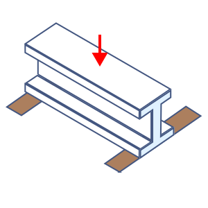
Đầu vào
Giá trị F
Chiều dài
Mô đun đàn hồi
Mô đun chống uốn
Mô men quán tính mặt cắt quanh trục yếu
Hằng số vênh
Mô đun cắt
Hằng số xoắn Saint-Venant
Mô men đầu dầm lớn hơn
Mô men đầu dầm nhỏ hơn
Kết quả
Độ mảnh giới hạn đàn hồi
Độ mảnh giới hạn dẻo
Hệ số hiệu chỉnh
Mô men chảy dẻo
Mô men mất ổn định xoắn
Độ mảnh của cấu kiện chịu uốn
Độ mảnh giới hạn
Ứng suất cho phép ngắn hạn
Ứng suất cho phép dài hạn
Ghi chú
- Thuật ngữ “cường độ ứng suất” dùng trong Tiêu chuẩn AIJ thiết kế kết cấu thép theo ứng suất cho phép được viết gọn thành “ứng suất” trên trang này.
- Với cấu kiện chịu uốn quanh trục khỏe (trừ thép hộp), công thức tính ứng suất cho phép phía nén thay đổi tùy theo tương quan lớn nhỏ giữa với và . Ứng dụng tự chọn đúng công thức giúp bạn.
- Dấu của (M2/M1) là âm trong trường hợp cong đơn và dương trong trường hợp cong kép. Ứng dụng tự áp dụng dấu này giúp bạn.