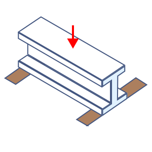
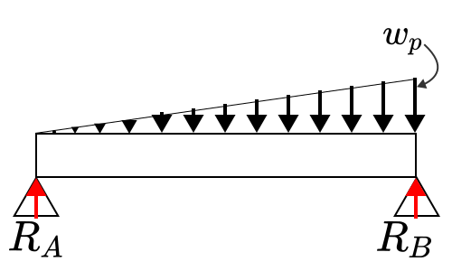
Simply supported, triangular load — Aluminium extrusion
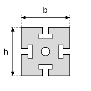
Deflection and stress of an aluminium extrusion (MISUMI HFS, SUS SF) used as a beam. Load case: Simply supported, triangular load. The grooved section is too involved to derive from its dimensions, so the section properties published by the manufacturer are used.
Input
Distributed load
Beam length
Young's modulus
Height (bending direction)
Width
Acceleration due to gravity
Result
Beam mass
Distributed load from the beam's self-weight
Second moment of area
Section modulus
Reaction force A
Reaction force
Maximum bending moment
Maximum deflection
Maximum bending stress
- The following is from 8.1 "Deflection of beams" of the AIJ Standard for Allowable Stress Design of Steel Structures (2019).
- Under long-term loading, the deflection of a beam shall not exceed 1/300 of the span, or 1/250 for a cantilever. Purlins, girts and the like may go beyond this limit so long as the finish is not affected.
- Where live load acts dynamically, the resulting vibration of the beam shall be checked so that comfort, the operation of precision equipment and productivity are not impaired.
- For crane runway girders the limit is 1/500 of the span for hand-operated cranes, and 1/800 to 1/1 200 for other electric cranes, according to the circumstances.