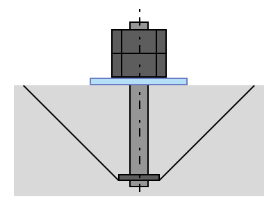
Exposed type
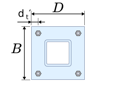
Input
Base plate width
Base plate length
Modular ratio
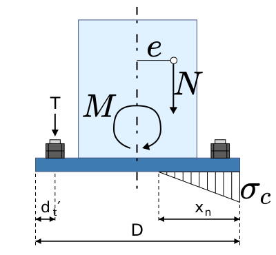
Bending moment
Axial force
Distance from the tension edge to the centroid of the anchor bolt group
Number of bolts on the tension side
Number of bolts on the compression side
Nominal anchor bolt diameter
Effective sectional area of the anchor bolt
Specified strength of the anchor bolt
Specified design strength of the concrete
Result
Eccentric distance
Total shank area of the anchor bolts on the tension side
Neutral axis depth
Compressive stress
Short-term allowable compressive stress
Total pull-out load on the anchor bolts
Yield tensile capacity of the anchor bolt
Shear capacity from friction
Sum of the shear capacities of the anchor bolts
Yield shear capacity
Verification
Press Calculate to see the check.
Notes
- The method follows 7.2, design of exposed column bases, of the AIJ Recommendation for Design of Connections in Steel Structures. The stress states are cases i) to iii) of its Fig. C7.9, the elastic stiffness is Eq. (7.2), the full plastic flexural capacity Eqs. (7.10) to (7.12), the maximum flexural capacity Eqs. (7.13) to (7.15), the shear capacity 7.2(4)2) with Eq. (7.16), and the anchorage Eqs. (C7.2) and (C7.3) of the commentary. The cubic that locates the neutral axis comes from the AIJ Standard for Structural Calculation of Reinforced Concrete Structures, which the Recommendation cites.
- Anchor bolt properties are from JIS B 1220-2015, structural double-end anchor bolt sets. Three different sectional areas are used. The shank area for the neutral axis, the stresses and the full plastic tensile capacity; the effective sectional area for the yield and maximum tensile capacities; and the effective shear area for the shear capacity, according to where the shear plane falls.
- The friction coefficient depends on the state. It is 0.4 for the yield shear capacity and 0.5 for the maximum shear capacity. In both cases the larger of the friction capacity and the sum of the anchor bolt shear capacities is taken.
- Counting the anchor bolt shear capacity calls for a detail that makes it possible. The base plate has to be stopped from moving — by welding on a washer plate whose hole matches the bolt diameter, for instance. Without that, check on the friction capacity alone. Design Example 1 of the Recommendation does exactly that: friction alone meets the required shear, and the anchor bolt term is not used.
- The equation for cone failure differs between standards. This page uses Eq. (C7.3) from the commentary to the AIJ Recommendation, with a reduction factor of 2/3 and 0.7Tr added for the column main bars. The equation in the MLIT Standard for Seismic Design of Government Buildings uses 0.6 and carries no term for the main bars; the Anchor bolt pull-out page on this site implements that one. Neither is more correct than the other — follow whichever standard the design is based on.
- Under tensile axial force, the allowable stress fields are not shown. The Recommendation only draws the elastic stress distribution for tensile axial force — cases iv) to vi) of Fig. C7.9 — without giving equations for the compressive stress, the neutral axis or the bolt tension. Design Examples 4 and 5, which do cover column bases under tension, do not use Fig. C7.9 either: they solve the bolt group as eccentric tension. The ultimate capacities — full plastic flexural, maximum flexural and maximum shear — are worked out under tensile axial force as well. They follow Eqs. (7.10) to (7.15), and regions (i) to (iii) of Eqs. (C7.9) to (C7.14) in the commentary.
- The base plate thickness is out of scope. Design it separately, as a steel plate carrying the out-of-plane bending from the bearing reaction of the concrete beneath and the tension in the anchor bolts, and keep it elastic. Side-face blowout of the concrete is out of scope too.
- What the steel standards call "stress intensity" appears in the result fields here as σ, following the symbols.